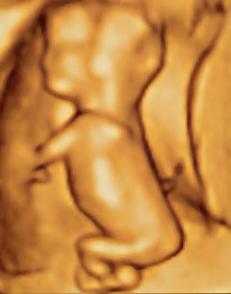
DICOM images are stacks of grayscale images used to define internal structures of the body.
3D files allows doctors to visualise and allow patients to visualise. 3D prints allow doctors to forecast if a certain approach would work for a special patient. 3D printing allows permanent restoration of a disease or condition. 3D printing allow simulation of a surgical procedure, endoscopy, bronchoscopy before actual procedure or for education purposes only. Instructing one or multiple trainees is possible trough 3D printed model of the condition. Bioprinting of live tissue has potential in the future of regenerative medicine.
Main areas of use for 3D printing:
- Preoperative planning
- Medical education
- Patient communication
It is really exciting to be empowered by a new kind of technology.
Data aquisition is the most important step in preparing a printable file, since data aquisition is irreversible or at best hard to repeat.
Selecting the modality:
- Ultrasound
- Computed tomography
- MRI
Selecting slice thichness and resolution.
If you think you can prepare a 3D model from 10mm thickness CT scan with smoothing and post processing you are wrong. Many 3D printers are capable of printing at 1/10mm thickness or 100μm. Scanning at a 51 cm area at 512 matrix produce pixels of 1mm resolion. Scanning the same area at 1024/2045 matrix would reduce voxel width to 0,5/0,25 mm or 500μm/250μm respectively.
Once you have the data in DICOM format you have to select a software for generating the 3D file. This is called 3D Reconstruction Software. I use Osirix and I am trying to learn 3DSlicer too.
- 3D Slicer (Surgical Planning Laboratory)
- MITK (German Cancer Research Centre)
- Osirix (Pixmeo)
- MIPAV (NIH CIT)
- MeVisLab (MeVis Medical Solutions AG)
- InVesalius (CTI)
If you have a fixed threshold value for your contrast such as 250-300HU for bone and minus 500 for skin on CT you can go ahead and export a file using the threshold value. Otherwise you have to do a segmentation manually, automatically or semiautomatically. Usually this is needed for soft tissues or small structures and organs with near simialar values. Segmentation need special training but selecting a fixed threshold is easy.
To be printable, a 3D file should be water tight such as a ball or balloon with no holes in it. There will large holes in your model if the aquired organ is cut in any way. Such as end of a long bone not scanned in entirely. Holes should be fixed in a third party software such as blender or meshmixer. Both are free.
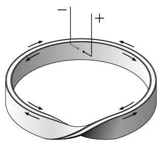
Your model might contain manifold errors. Non-manifold polygons have a configuration that cannot be unfolded into a continuous flat piece. In the “T” shape error, more than two faces share an edge. An edge is connected to 3 polygons. In “bowtie” shape error, two faces share a single vertex without also sharing any edges. In third manifold error a single shape has non-contiguous normals. i.e. one polygon is looking outside while the neighbour polygon is looking inside. Klein Bottle and Möbius strip both have this kind of errors.
Due to artifacts in CT, MRI and US you will also have disconnected floating artifacts. These are small parts seperate from main object floating freely in the air. They should be avoided whenever possible during mesh generation. If not they should be cleaned afterwards.
The software you use for editing is called 3D editing software. Editing process should clean and repair the model of holes and maniold errors and delete floating parts but should not damage the specific form and shape of original image.
You will need to choose a printing technology. If you need to create a metal prosthesis you have to print in metal. Printers that work directly with metals are generally expensive. However less expensive printers can be used to make a mold, which is then used to make metal parts.
Here is a table from Wikipedia comparing different printing techonolgies.
| Type | Technologies | Materials |
|---|---|---|
| Extrusion | Fused deposition modeling (FDM) or Fused Filament Fabrication (FFF) | Thermoplastics, eutectic metals, edible materials, Rubbers, Modeling clay, Plasticine, Metal clay (including Precious Metal Clay) |
| Robocasting or Direct Ink Writing (DIW) | Ceramic materials, Metal alloy, cermet, metal matrix composite, ceramic matrix composite | |
| Light polymerized | Stereolithography (SLA) | Photopolymer |
| Digital Light Processing (DLP) | Photopolymer | |
| Powder Bed | Powder bed and inkjet head 3D printing (3DP) | Almost any metal alloy, powdered polymers, Plaster |
| Electron-beam melting (EBM) | Almost any metal alloy including Titanium alloys | |
| Selective laser melting (SLM) | Titanium alloys, Cobalt Chrome alloys, Stainless Steel, Aluminium | |
| Selective heat sintering (SHS) | Thermoplastic powder | |
| Selective laser sintering (SLS) | Thermoplastics, metal powders, ceramic powders | |
| Direct metal laser sintering (DMLS) | Almost any metal alloy | |
| Laminated | Laminated object manufacturing (LOM) | Paper, metal foil, plastic film |
| Wire | Electron beam freeform fabrication (EBF3) | Almost any metal alloy |
The cost with different printing technologies vary widely. I will not discuss this aspect of 3D printing. Main factors to consider when choosing a printer:
- Printing speed,
- Printing resolution
- Printer availability,
- Material availability,
- Cost of printer and materials,
- Printer bed size,
- Noise and fumes,
- Printed material characteristics,
- transparency,
- multicolor,
- hardness, flexibility
- multimaterial capabilities,
- biocompatibility,
- sterilization capability,
- high-temperature
- chemical
- radiation
- molding or casting properties,
- Ease of printing and maintenance.
Preparing your model for printing.
Reduce your mesh. Not all polygons are needed to accurately represent your model. Most models need something between 500.000 to 1000.000 polygons for accurate representation. You can remesh and reduce your model to reduce file size and further processing times without copromising the model shape.
You have to decide whether you need an original size model, reduced size or enlarged model. If you need an original size model but your printer can not print big enough models you can consider dividing your model into smaller parts and printing each part seperately.
Assuming you are using an FDM printer, the one most widely used around, you have to learn the concept of fused deposition. Softened plastic is deposited layer by layer, one on top of the other. It can not be deposited on middle of the air as it would drop down while soft. It can not deposited on long horizontal parts or it would drop down. It can not make long bridges with points too far away. My printer can bridge parts 1cm apart and can handle angles near 22 degrees to horizontal.
In any oher part of the mesh you have to add removable support structures for the model to be buildable. These are called overhangs. Too many support structures are hard to clean after manufacturing. Too few supporting parts cause defective and hanging filaments. Aligning the model so that it requires the least amount of support is a good strategy. Placing supports as far as you can is another. Some complex models are best printed with dissolvable support.
Many models need not be %100 filled. You can decide on an infill percent and shell thickness optimized for strength and material consumption. You can also print a raft to easily seperate the model from printing base.
Repairing and refining for print:
- Closing (Holes, gaps and open ends)
- Removing unwanted parts (Internal or external)
- Fixing (Inverted normals, non-manifolds)
- Remeshing and smoothing
- Resizing and scaling if necessary
- Slicing if necessary
- Rotating for best orientation
- Moving to platform
- Adding support
- Deciding on infill percent, generate raft
- Printing
- Cleaning the printed object
As the technical complexity and price of 3D printing is decreasing we can envision 3D printing being a routine bedside tool. Manual processing which is needed to prepare the model needs to be automated and become fail proof for more widespread use of the tool.


Hiç yorum yok:
Yorum Gönder